Chapter 12: Storage Devices
This chapter, we discuss the characteristics of persistent storage devices, and how to design our system to be performant in context of the underlying hardware.
12.1 Magnetic Disk
The below diagram showcases the structure of a magnetic disk, also known as a hard drive.
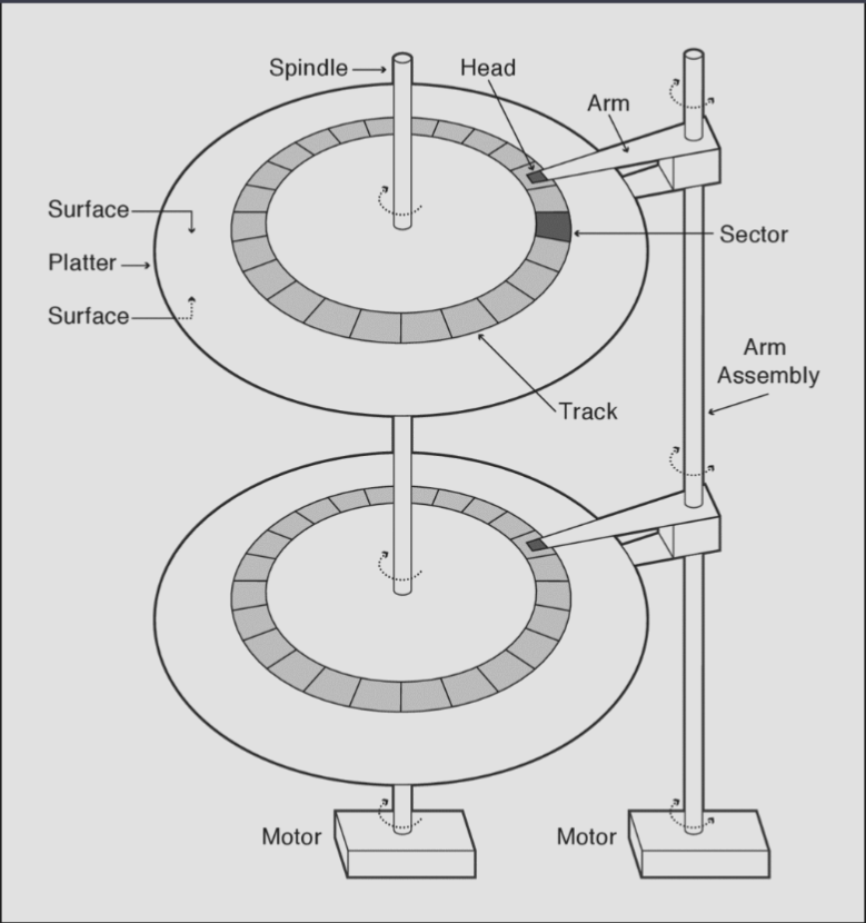
A magnetic disk drive is composed of multiple magnetic disks, known as platters, stacked on top of each other. A spindle connects all the magnetic disks through the middle, and a motor continuously spins the disks when the drive is on. On the side, there is another rod known as the arm assembly, which is connected to a motor that rotates it across a 180 degree range on demand (depending on requests) and holds an arm for each platter. At the end of each arm is a head, which is able to read/write data by sensing/introducing a magnetic field on the corresponding surface of its platter. Each platter has two surfaces, one on each side. typically, the disk head will "float" on a layer of rapidly spinning air created by the spinning of the disk platter—this allows the disk head to remain extremely close to the platter.
Each surface is divided into concentric circles of tracks, which are each divided into sectors, typically 512 bytes. The arm's rotation allows switching tracks, and the disk's spinning allows reaching the desired sector. Notably, disk hardware cannot read/write individual bytes/words—it must read/write an entire sector.
One reason for this is that disks encode each sector with error correction code data.
Logical sector 0 subsequent tracks are also staggered by the amount of time it takes the disk to move the head to a different track or switch from to the head on the opposite surface to improve sequential access speed; this is known as track skewing. Each disk also includes spare sectors distributed across surfaces to account for broken sectors; slip sparing helps preserve good sequential access performance by remapping all sectors between the bad sector and then next spare sector.
Disk drives also frequently include a few MB of buffer memory, which is used by the disk controller for
- Buffering data being read from / written to the disk
- Track buffering, i.e. buffering sectors that have been read by the disk head (i.e. while rotating to the desired sector) but were not requested by the operating system (but may be requested in the near future).
- Write acceleration, i.e. the disk stores data to be written in the buffer and acknowledges the writes to the OS before data is actually written to the platter; later, the disk controller flushes the writes.
Server drives implementing SCSI/Fibre Channel interfaces and commodity drives with SATA interfaces use a safer write acceleration technique known as tagged command queueing (TCQ) or, for SATA, native command queueing. This allows an OS to issue concurrent requests and for the disk to process them out-of-order; it may be configured to only acknowledge writes when blocks are written to the platter.
Disk Access and Performance
An OS request would ask the disk to read/write one or more consecutive sectors. A disk's sectors are identified by logical block addresses (LBAs), which specify the surface, track, and sector.
Servicing a request requires three steps: seeking to the right track, waiting for the desired sector to rotate to the head, and transferring the blocks. That is, disk access time is
- Seek
A seek involves a disk moving its arm to the desired track. A disk's minimum switch time is the time required to move the head to an adjacent track, while its maximum switch time is the time required to move between the innermost/outermost tracks. A disk's average seek time is frequently approximated as the time required to seek 1/3 of the entire way across the disk. Also, the head switch time is the time it would take to switch to a head on a different surface, and has a cost similar to a minimum seek, due to slight misalignments between surfaces.
Average seek time is not typically a good metric, because it assumes zero locality in a workload—which is typically not true. The minimum seek time is typically more representative.
A cylinder is a set of tracks on different surfaces with the same track index. Early file systems placed related data on different surfaces but within the same cylinder; however, this has largely fallen out of popularity since switching disk heads is effectively a 1-track seek now; thus, most choose to locate such data in adjacent tracks on the same platter instead.
-
Rotate
As you may recall, the disk is always spinning when on. However, after the disk seeks to the correct track, it may not be at the right sector! So, it must wait for a bit—this is called rotational latency. -
Transfer
Once the disk reaches the desired sector, the data must be transferred to/from disk from/to buffer memory. In order to amortize seek and rotation time, which are typically the dominating factors in latency, disk requests are typically batched into requests for multiple sequential sectors. The time to transfer one or more sequential sectors once the disk head finds the first sector is the surface transfer time.The time to transfer data between the host's memory and the disk's buffer is the host transfer time. This is on the critical path for reads and possibly writes if the disk does not use write acceleration. Latency, though, is not typically affected by this much since most disks overlap host latency with the other aforementioned processes and this metric is typically not a bottleneck.
We've talked a lot about prioritizing sequential access performance. But what about workloads with largely random accesses? Well, as alluded to previously, disks typically deliver bad performance with random access workloads—this is because the seek and rotation latencies are not amortized.
Disk Scheduling
As aforementioned, seek and rotate latencies are very expensive. So, it begs the question—how can we optimally schedule/order the disk requests we must serve to optimize for low latency and high throughput?
The simplest scheduling algorithm is just FIFO, but this can, of course, result in very poor performance depending on the workload. The worst case involves requests that alternate between the outer and inner tracks of a disk.
SPTF (shortest positioning time first) or SSTF (shortest seek time first) may seem effective, given that SJF was optimal for throughput for CPU scheduling. In essence, given the current position of the disk head and platter, service the quickest pending request. However, not only do these algorithms suffer from starvation, like SJF, these algorithms' scheduling does not necessarily minimize the aggregate seek and rotation times across an entire workload. This is because choosing to serve one request actually affects the seek/rotation times of other requests, in contrast to SJF!
Thus, some entirely disk-specific algorithms have been developed: elevator-based algorithms.
In essence, an elevator-based algorithm functions similarly to how an actual, real-life elevator services requests: when going up, it continues until all pending requests to go to above floors are serviced; then, when going down, it continues until all pending requests to go to below floors are serviced.
SCAN functions in the exact same way; the disk arm sweeps from the inner to outer tracks, servicing all requests between the current position and the outer edge. Then, it does the equivalent when sweeping from the outer to the inner tracks.
CSCAN, i.e. circular scan, functions similarly; except, the disk only services requests when the head is traveling in one, predetermined direction (inner to outer, or outer to inner). When the last request in this direction is service, the disk seeks to where it started without servicing requests. The advantage of CSCAN over SCAN is that, after a pass in one direction, the disk head would currently be in a region of disk with sparse requests, since it was just serviced; CSCAN moves the head to an area with (probably) greater request density. Also, CSCAN, by the same idea, is fairer.
R-SCAN and R-CSCAN are variants that also account for rotation time. (SCAN and CSCAN primarily attempt to amortize seek time). In essence, the R variants allow small seeks in the "wrong direction" if a sector on a previous track is very close with regards to the rotation proximity.
12.2 Flash Storage
Flash storage is a type of solid state storage—it has no mechanical components and stores data via its circuitry and electricity. With its lack of mechanical parts, flash storage has much better random I/O performance than disks, can use less power, and are less susceptible to physical damage. At present, though, it remains more expensive.
The minimal unit of storage in flash is a floating gate transistor, known as a cell. It typically stores a single bit (single-level flash storage) but can also store multiple (multi-level flash storage).
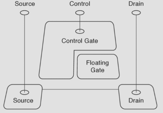
There are multiple types of flash storage, depending on the control gate used to store a bit. NOR flash allows individual words to be read/written, and is useful for storing device firmware since it can be executed in place. NAND flash must be read/written on a page granularity, but is denser and is thus more commonly seen.
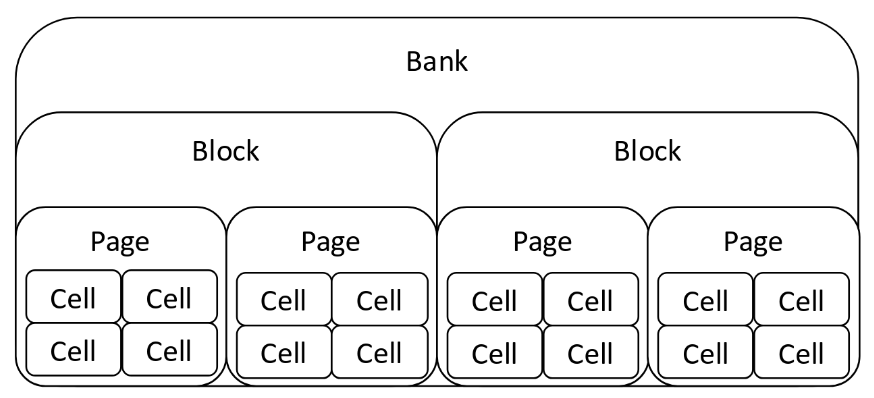
Here is the structure of a bank of flash storage—each flash chip has multiple banks, which can be accessed in parallel.
There are 3 primary operations associated with flash storage
- Erase erasure block. Before flash memory can be written, it must be erased by setting each cell to a logical 1. Moreover, flash memory can only be erased in units called erasure blocks, which are often quite large. Erasure is also slow, on the order of several milliseconds. (Erasure is also what gives flash memory its name!)
- Write page. Once erased, NAND flash can be written page-by-page, an operation on the order of tens of microseconds.
- Read page. NAND flash can be read similarly on a page-by-page basis, with the same latency as writing a page.
The necessity of erasing an entire erasure block before writing is the biggest challenge facing flash storage. Most flash storage devices implement a flash translation layer (FTL) that maps logical flash pages to different physical pages on the flash device. Then, when a logical page is overwritten, the new version is written to a free, already-erased physical page, and the logical page is remapped to the physical page. This is known as write remapping, and significantly improves flash performance (since erasure is no longer necessary for every single write).
It's also necessary to discuss the durability of flash storage. Flash memory can retain its persistently stored data for years without power; however, flashing and writing memory involves high current loads, which results in circuit degradation—consequently, a cell can wear out and become unreliable! (Also, multi-level cells wear out faster).
Also, reading a cell many times can disturb nearby cells' charges, inducing a read disturb error that changes a cell's value due to excessive reads to nearby cells.
Flash devices implement several techniques to account for their durability issues.
- Error correcting codes. Each page has a few extra bytes for extra correcting codes, to resolve any bit errors.
- Managing bad page and bad erasure block. The device firmware will mark a failing page/erasure block as bad.
- Wear leveling. As aforementioned, FTL uses write remapping to keep write latency low. This has the added benefit of ensuring that a frequently used hot page does not wear out a physical page on the flash device. Some devices extend this by migrating unmodified pages to prevent read disturb errors.
- Spare pages and erasure blocks. Flash devices frequently possess spare pages and spare erasure blocks. This serves 2 purposes: extra space for device wear leveling management, even if the device is logically full and enables bad page/erasure block management to function without shrinking the device's logical capacity
Wear also affects a flash device's performance: accesses may require additional retries (due to errors) and as spare pages and erasure blocks are consumed by bad ones, the wear leveling algorithms have less spare space and must frequently garbage collect live pages.