Chapter 13: Files and Directories
Four major challenges
- Performance
- Flexibility
- Persistence
- Reliability
We will discuss the first three in this section.
13.1 Implementation Overview
A file system's primary job is to map a file name and offset to a persistent physical storage block. It does this in two steps
- It maps a file name and offset to a file number, typically traversing through several directories to retrieve the file number. The directories are generally arranged in a tree-like structure (though, technically a DAG)
- The file number is associated with an index structure, which is a persistent data structure that maps the file number and offset to a specific storage block. This is frequently some sort of tree.
File systems also use free space maps to track free storage blocks, which allow file systems to allocate and free blocks as files grow and shrink. This is typically implemented as a bitmap, and frequently allows finding free blocks around a desired location, to support spatial locality.
File systems further utilize several locality heuristics to group data for optimizing performance; for instance, magnetic disk drives are, at times, defragmented to improve performance of future accesses.
13.2 Directories
Directories are simply a way for file systems to group related data together, to make it easier for users. They're typically arranged in a tree-like structure, and each directory is actually stored as a file itself, known as a directory file!
Directory API
In order to prevent corruption of the special directory file structure, there exists a specialized API for modifying directory files. In particular, there aremkdir,link,unlink, andrmdirsyscalls.
But how is a directory file actually formatted? Early implementations simply had linear lists of (file name, file number) pairs. For instance, Linux's original ext2 file system was a linked list of these pairs. (Linked list instead of an array because directory entries could be removed). This is fine for directories with few entries, but as systems grew, some workloads generated thousands of files in a directory—meaning access times slowed down (, so scales linearly with number of entries). Thus, more recent file systems organize directory entry contents as a tree, typically some sort of balanced binary search tree.
Also, as mentioned in Chapter 11, there exists two types of links that can "duplicate" files. We include the same explanation here.
File systems, however, are not exactly trees. They are, in fact, DAGs—directed acyclic graphs. This is due to the possibility of multiple hard links to an underlying file, i.e. a mapping between a name and an underlying file. In other words, it's possible for multiple paths to point to the same file. Note that these hard links are typically restricted to avoid cycles, and hence file systems are usually DAGs.
Many systems also support symbolic or soft links. This is a directory mapping that, instead of mapping a file name to an underlying file, maps a file name to another file name. Though moving the other file name may result in dangling links, symbolic links have two key advantages: systems typically allow symbolic links to directories (because these won't have cycles... traversing a symbolically linked directory will just bring you to the other directory, in contrast to a hard link) and a symbolic link can refer to a file in a different file system or volume (since it just maps to the file name, rather than the underlying file which may have different structure).
Now, you may understand how exactly this works. Any hard links to a file map to the same underlying file number, while a symbolic link just maps to another file name itself (which eventually resolves to a file number).
Hard links make storing file metadata in directory entries difficult, as it would require duplicate information and updates.
13.3 Files
Now, we discuss the more complex part of file systems: how to organize the data associated with a file number. This part of the file system is complex, and sees many different designs, because it must attempt to achieve several goals.
- Support sequential locality
- Provide efficient random access
- Limit overheads for small files, but facilitate very large files
- Enable the storage of per-file metadata
This section, we'll discuss several popular designs.
- FAT (Microsoft File Allocation Table) is the oldest (late 1970s), and uses a simple linked list index structure that supports granularity at the block level. It uses a FAT array for managing free space, and the only method for supporting sequential locality is periodically defragmenting the file system. While largely a legacy choice for a computer's primary file system, it remains prevalent for small USB drives, embedded devices, and boot drives where file systems are expected to be kept relatively compact.
- FFS (Unix Fast File System) was released in the mid 1980s, and inspired the ext2 and ext3 file systems that are default on most Linux systems. It uses a tree-based multi-level index for its index structure (explained soon :>), which can be described as fixed and asymmetric, uses a fixed bitmap for managing free space, supports block-level granularity, and uses block groups and reserved space to improve sequential locality.
- NTFS (Microsoft New Technology File System) was introduced in the early 1990s to replace FAT, and is the default today on Windows systems. It uses a dynamic tree-based structure, and supports extent-level granularity, effectively variable-sized blocks (extents are to blocks as segments are to pages). It also uses a bitmap for tracking free space, and uses best fit and defragmentation as its locality heuristics. Its use of a flexible tree and extents has inspired Linux's ext4, XFS, Apple's Hierarchical File Systems (HFS/HFS+), and more.
- ZFS (Zettabyte File System) was designed by Sun Microsystems in the early 2000s. It featured a dynamic tree, block-level granularity, a log-structured space map for free space management, and locality improvements via block groups and a write-anywhere policy (explained later). However, its main innovation is that its a COW (copy-on-write) file system, which provides strong integrity and optimizes write performance.
In summary,
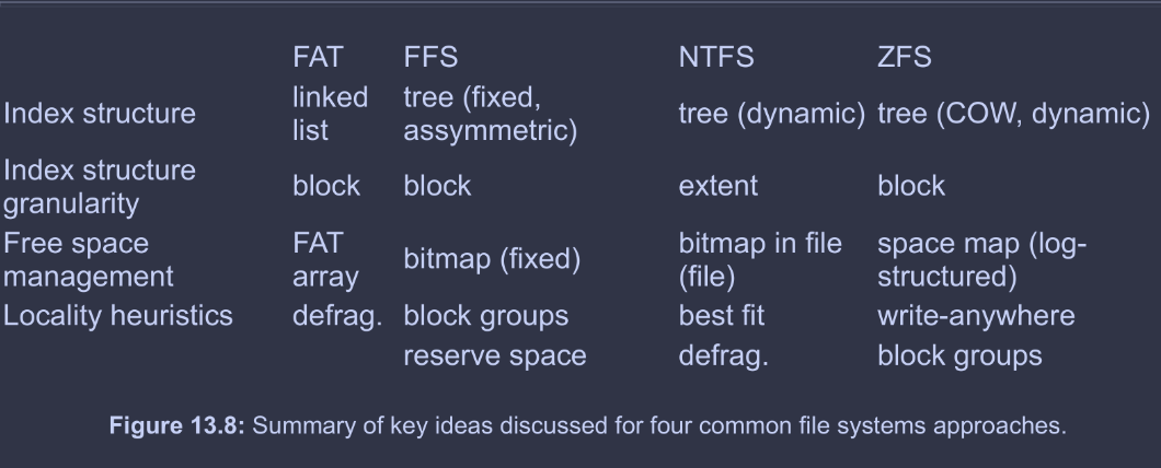
FAT and NTFS refer to blocks as clusters, NTFS refers to extents as runs (proprietary Microsoft as usual...). The textbook uses block and extent, which are more commonly used, and these notes will follow this.
FAT
FAT is quite simply named after its index structure, the file allocation table. Its effectively an array of 32 bit entries in a reserved area of the volume. Each file is backed by a linked list of FAT entries; each entry consists of just a pointer to the next FAT entry (really, its index in the FAT, or a special EOF value). Meanwhile, the FAT itself had a 1-to-1 correspondence with the backing device; the first FAT entry corresponded to the first block, etc.
The file number found by traversing directories was the index of the head FAT entry for the file. Free space was simple; unused FAT entries are marked , and so it sufficed to linearly scan the FAT array for a free entry.
Generally, FAT's locality heuristics were simplistic and resulted in significant fragmentation (e.g. next fit algorithm, start from last allocated entry and return next free entry). Hence, the only way to improve FAT's locality was to periodically defragment.
In summary, the FAT system, while simple and portable to practically all operating systems, has several limitations.
- Poor locality
- Poor random access
- Limited file metadata and access control
No metadata like file owner/group id - No support for hard links
File metadata is stored in the directory entry since it cannot be stored in the FAT, so no hard links—how would you find all the other links when modifying metadata? - Volume and file size limitations
FAT-32, the most commonly used version today(?) supports at most blocks, i.e. with block sizes, and byte file sizes - No support for modern reliability techniques
i.e., those discussed in Chapter 14.
FFS
FFS's index structure is a multi-level index, a an asymmetric tree structure that provides good efficiency for small and large files. It can be succinctly summarized by the following diagram.
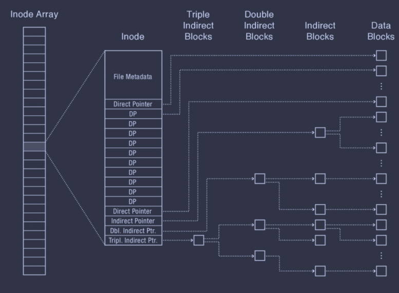
In essence, each inode represents a file. It begins with file metadata, several direct pointers, and then several different indirect pointers. The direct pointers directly store the block numbers of their corresponding data blocks. However, the indirect pointers have some level of indirection; the double indirect pointer, for instance, points to a double indirect block first, which itself contains pointers to indirect blocks, each of which contains pointers to the actual data blocks.
Also, note that all inodes are stored in an inode array that lives in a fixed location on disk, and a file number is called an inumber in FFS, and corresponds to that file's index in the inode array.
This asymmetric structure allows storing large, extensible files without significantly increasing the space or runtime overhead for smaller files. Small files only require one access per data block (using the direct pointers only) while larger files are able to support both efficient random accesses (since it's a tree structure) and good sequential accesses, since the degree of the indirect nodes are extremely large (i.e. reading an indirect block means hundreds of data blocks can be read before the next indirect block must be read).
FFS's tree also has a fixed structure, which is much easier to implement. Additionally, FFS can effectively support sparse files, i.e. files that are largely composed of empty space (null bytes), as these ranges of empty space can be represented as null pointers in FFS. In other words, FFS can perform lazy allocation of disk blocks.
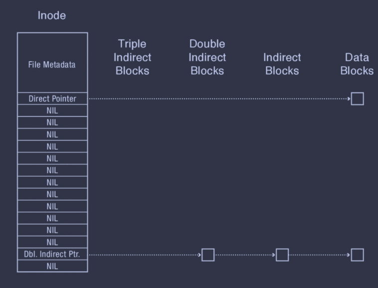
Sparse files do have some limitations, though. Not all file systems support them, so they're not very portable. Also, programs may not handle sparse files correctly, i.e. reading a sparse file and writing each byte to another file results in a non-sparse file with many null bytes.
Regarding free space management, FFS just uses a bitmap in a fixed, known location. Regarding locality heuristics, FFS has two: block group placement and reserved space.
Block Group Placement
This heuristic involves:
-
Dividing a disk into block groups (where blocks within the same group typically have good locality/low intra-group seek times)
-
Distributing metadata (inode array, free space bitmap) across block groups, where the metadata tracked within a block group typically corresponds to its block group
-
Placing files in a block group according to spatial locality, e.g. files within the same block group as its directory. Note that subdirectories are typically placed separately from their parent directories; otherwise, the block group may fill quickly.
-
Placing data blocks for the same file within the same block group. FFS uses a seemingly counterintuitive strategy of writing a block to the first free block in the file's block group. This heuristic sacrifices short term locality, as it fills up various holes in the start of a block group; however, it benefits long term locality, as this will reduce fragmentation and typically result in a long run of free space at the end.
The idea is that, for small files, its blocks will end up distributed across several holes—an acceptable sacrifice for smaller files. But, for large files, the majority of its blocks will end up in the consecutive free space at the end, providing the good sequential locality critical for larger files.
Reserved Space
This heuristic is simple. Since the block group heuristic is only really effective when there is enough free space on disk, FFS reserves some fraction of the disk space. If the actual disk free space falls below this fraction, FFS considers the disk full for all but a super user's processes. This allows the super user to reduce disk usage / increase storage capacity, while keeping the file system efficient.
Consider the following situation: the disk reads a block, does some processing, and then tries to read the next block. But, in the meantime, the disk has continued turning (as a magnetic drive constantly rotates), and the next block is already gone! How can we solve this?
Solution 1: Skip Sector Positioning (Interleaving). Essentially, just place blocks of a file on every other block of a track, i.e. leave blocks in between.
Solution 2: Read-Ahead. Predict that the application will require the next block, and read the block anyways. Many modern disk controllers have enough internal RAM to hold a complete track in memory!
Limitations
FFS, despite efficiently storing both small and large files and requiring zero defragmentation, has some limitations.
- It's inefficient for tiny files (e.g. files smaller than a couple data blocks)
- It's inefficient for files with large contiguous segments on disk (must break it up into blocks)
- It needs to reserve free space
NTFS
NTFS uses a tree like FFS, but this tree is flexible and tracks dynamically-sized extents, not blocks.
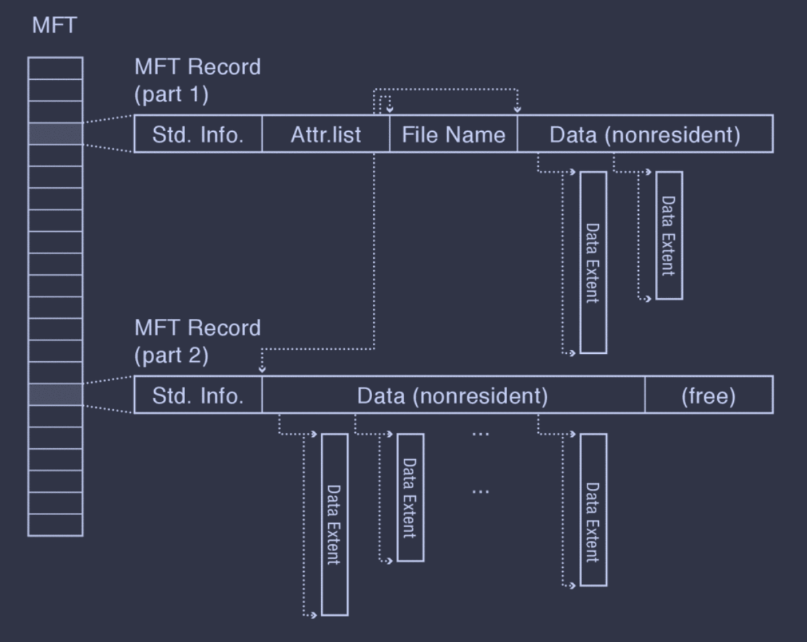
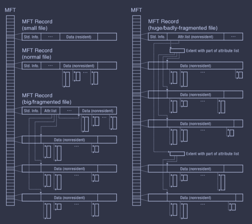
The root of the trees is stored in a master file table (MFT) similar to FFS's inode array. Each element in the MFT is a MFT record, which stores a sequence of variable-sized attribute records, which store data or metadata.
Attributes can be too large to fit in a record. These are known as nonresident attributes (while those that can fit are known as resident attributes), and a non-resident attribute stores extent pointers in its MFT record and its contents in those extents.
Beyond simple data attributes, there are a few common metadata attributes.
- Standard Information. This holds file creation time, owner ID, etc.
- File Name. An MFT can have multiple file name attributes, if there are multiple hard links to this file.
- Attribute List. A file's metadata may have many variable-sized attributes; thus, it may require more MFT records. In this case, NTFS stores the attributes in multiple MFT records, and the attribute list of the parent MFT record will include pointers to these MFTs.
The below diagram shows an example of a file with an attribute list and both resident and non-resident attributes.
A file in NTFS may go through four stages of growth, depending on size and fragmentation.
- Small file has all contents included in MFT record, with a resident data attribute.
- File has a small number of extents tracked by a non-resident data attribute.
- File becomes fragmented, i.e. too many extents, and has an attribute list in the root MFT record pointing to other MFT records with non-resident data attributes.
- File becomes huge or has extreme fragmentation, in which case the attribute list becomes non-resident.
Metadata Files
NTFS also stores all of its metadata, e.g. free space bitmap, root directory, volume bad blocks, etc., in a few files with well-known file numbers. Even the MFT is stored as a file, with file number 0. Though, to locate the MFT, the first sector of an NTFS volume includes a pointer to the first entry of the MFT (it's not actually possible to locate the MFT based off the file number... the file number is the index in the MFT!). However, storing the MFT in a file has its benefits; it makes it possible to expand and shrink the MFT as needed.
Locality Heuristics
Most NTFS implementations use some variation of best fit. To assist this, there's even a SetEndOfFile() API that allows specifying a file's expected size at creation time.
Also, to avoid MFT fragmentation, NTFS reserves part of the volume's start for MFT expansion. If the non-reserved area becomes, full, however, it halves the size of the MFT reserve area and continues. This is repeated until this is not possible (MFT takes up more than 50% of the reserve area).
Finally, Microsoft provides a defragmentation utility for its NTFS file systmes.
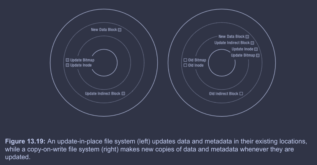
ZFS (COW)
Here's a quick visualization of update-in-place vs. copy-on-write systems.
Benefits of COW
- Small writes are expensive. Large sequential writes are simply much better than small random writes, and COW turns update-in-place's small random writes into large sequential writes.
- RAID. Redundant arrays of inexpensive disks (RAID) is a topic we'll discuss more in Chapter 14. However, point is, is that RAID is becoming increasingly popular, and it makes small writes even more expensive.
- Caches filter reads. Large DRAM caches handle most reads, but cannot entirely buffer writes—otherwise, this sacrifices durability/reliability. Therefore, write performance dominates.
- Flash storage. Flash storage's lifetime is improved by wear leveling, i.e. spreading writes evenly across cells. The FTL (flash translation layer) already uses COW—so COW file systems are, by nature, more compatible with flash. (At least I think this is why... I'm not actually sure though)
- Versioning. COW file systems enable versioning, e.g. Git commit histories. As storage capacities grow larger and larger, versioning becomes more appealing.
Implementation Principles
We'll discuss ZFS, a COW file system that uses an index structure like FFS.
First, ZFS replaces the typical inode array that serves as the root of FFS with an uberblock. Whereas FFS's inode array stored the inode data itself in the the inode array, ZFS, as COW system, cannot do this, since the inode data should not be updated in place. Instead, each entry of the uberblock (essentially) contains a pointer to the root dnode, which resolves (through a series of pointers) to a dnode array (which is essentially the inode array).
The root dnode is decoupled from the uberblock in order to keep the root dnode COW; a new root dnode can be created first, and then the pointer to the root dnode can be updated in the uberblock.
Notably, the uberblock itself is not in a fixed location; instead, an array of 256 uberblocks are kept in a fixed location, each with an associated checksum. On a root dnode update, the next uberblock is actually updated with a pointer to the new root dnode. This helps ZFS makes the uberblock COW too—the idea is that this will protect the uberblock from errors after system crashes. On restarts, ZFS scans the uberblock array for the uberblock with a valid checksum and the highest sequence number.
Note that the dnode essentially just replaces the inode in functionality. Each dnode has space for three block pointers, and a field for the depth of the tree rooted at this dnode. If the depth is...
- The dnode stores the file's data itself.
- The dnode's block pointers are direct pointers.
- The dnode's block pointers are indirect pointers.
- The dnode's block pointers are double indirect pointers.
- etc.
- etc.
- etc.
- etc.
for up to six levels of indirection!
Also, data block and indirect block sizes are variable, actually; their sizes are specified in a file's dnode.
The root dnode itself is the root of a tree that eventually resolves to leaves of dnode arrays. Together, these dnode arrays represent the inode array of FFS. Each dnode in a dnode array represents a file, and is the root of a tree that resolves to leaves of data blocks. An example (though simplified from ZFS's full structure) is displayed below.
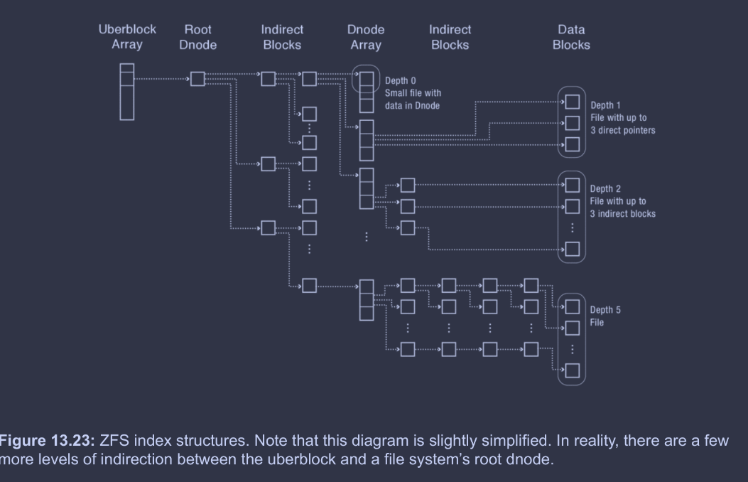
The uberblock is the root of the whole file system. The uberblock array just allows for the uberblock to be COW, with checksums to denote which uberblocks are valid after crashes. The uberblock contains a pointer to a root dnode; this ensures the root dnode is COW as well. The root dnode, through some number of indirect blocks in a tree structure, resolves to leaves, each representing a subset of the dnode array. The motivation for turning the dnode array into a tree structure is that it's more efficient for COW (see the diagram below for visual clarification). Each element in the dnode array represents a file, and, through 0 or more indirect blocks in a tree structure, resolves to leaves of data blocks (or even data within the dnode itself).
Finally, here's a diagram showing the process of updating the last block in a 2-level ZFS file.
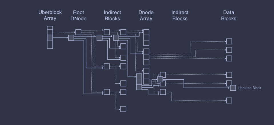
Critically, note how the tree structures for storing the dnode array and the data blocks for each file is incredibly helpful for making COW efficient, as it reduces the amount of content that must be copied.
ZFS Space Map
ZFS's space maps are designed to efficiently scale with extremely large storage systems. They use three key ideas.
- Per block group space maps. ZFS has a space map for each block group, and restricts new block allocation to a subset of block groups at any given time, and keeps those block groups' space maps in memory (reducing allocation overheads).
- Tree of extents. Each block group's free space map is represented as an AVL tree of extents. This allows efficient resolution of a free extent of desired space as both time and space scale logarithmically with the block group size, rather than linearly as it would with bitmaps. (Technically, worst case space scaling is linear; however, on average space scaling is logarithmic).
- Log-structured updates. Caching a space map in memory (i.e. first bullet point) effectively speeds up allocations, but not frees. Thus, rather than updating the on-disk space map, ZFS appends space map updates to a log. When a block group is activated for allocation, ZFS performs all the logged updates at once, effectively batching all updates until the next use of the space map.
ZFS Locality Heuristics
COW systems like ZFS, though, must perform a lot of work just to update a block. ZFS includes some nice heuristics to optimize write behavior.
- Sequential writes. As alluded to in the [[#Benefits of COW|beginning of this section]], the updates can frequently be grouped into a single write of a free range of sequential blocks on disk. (Excluding the uberblock). Sequential writes are much faster than random writes, and thus make up for the increased quantity of metadata updates.
- Batched updates. ZFS also batches file writes. Rather than writing each update to disk one-by-one, ZFS batches several seconds of updates and writes the entire update to disk, effectively amortizing the updates to all the dnodes and indirect blocks.
Additionally, ZFS cleverly chooses where to write new block versions in three steps.
- Choose a device. ZFS uses a WRR (weighted round robin) policy based on the amount of free space left in each device. ZFS also places ~512 KB on one device before switching to maintain good locality for future reads—almost like a quanta in scheduling RR!
- Choose a block group. ZFS's first choice is to use the most recent block group. If it's too full of fragmented, though, ZFS selects a new block group, biasing towards those with more free space, closer to the outer edge of the disk (for improved bandwidth), and that have recently been used (to limit seek distance).
- Choose a block within the group. First fit allocation until almost full, then ZFS switches to best fit.